|
3-154
ENGINE AND ENGINE OVERHAUL
|
| Rotors |
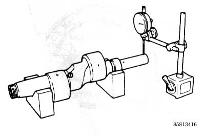
| See Figure 357 |
| 1.
Check the rotor for signs of blow-by around the side and corner seal
areas. |
| 2. The color of the carbon deposits on
the rotor should be brown, just as in a piston engine. Usually, the
carbon deposits on the leading side of the rotor are brown, while those
on the trailing side tend toward black (as viewed from the direction
of rotation). |
| 3. Remove the carbon on the rotor with
a scraper or extra fine emery paper. Use the scraper carefully when
cleaning the seal grooves to avoid any damage. |
| 4. Wash the rotor in solvent and blow
it dry with compressed air. |
| 5. Examine the internal gear for cracks
or damaged teeth. If the internal gear is damaged, the rotor and gear
must be replaced as a single assembly. |
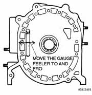
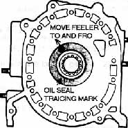
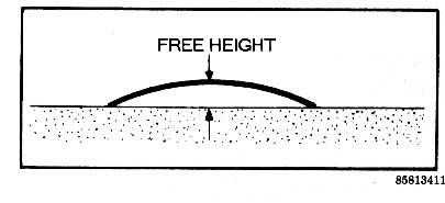
| 6. With the oil seal removed, check the
land protrusions by placing a straightedge over the lands. Measure the
gap between the rotor surface and the straightedge with a feeler gauge. |
|
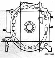
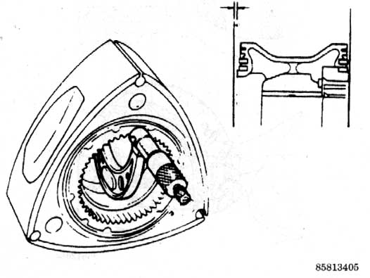
7. Check the clearance
between the housings and the rotor on both of its sides:
|
| a. Measure the rotor width with a vernier
caliper at the points indicated in the corresponding illustration. |
| b.
Compare the rotor width against the width of the previously measured
rotor housing. |
| c.
Replace the rotor, if the difference between the two measurements is
not 0.0047-0.0074 in. (0.12-0.19mm) for the 1979-85 carbureted engine
or 0.0047-0.0083 in. (0.12-0.21 mm) for the 1984-90 fuel injected engine. |
| 8. If the clearance exceeds
the specified values, replace the rotor. If the clearance is less
than specification, it means that the internal gear must be removed.
To dislodge the gear from the rotor bore, smack it lightly with a plastic-faced
hammer, being careful not to damage the rotor. With the gear removed,
recheck the side housing-to-rotor clearance again. |
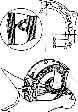
| 9. The corner seal bores can be checked
with a gauge (tool number 49 0839 15 or equivalent), available from
Mazda. If
neither end of the gauge can be fit into the bores, it is safe to reuse
the original corner seals. If the "go" side of the gauge does
fit into the bore, but the larger "no go" side does not, use
new seals. If both sides of the gauge fit into the bores, the rotor
must be replaced. |
| 10. Check the rotor bearing for wear,
flaking, scoring or damage. Replace the bearing if these conditions
are found.Check the bearing oil clearance by measuring the appropriate
bearing journal diameter on the eccentric shaft with a micrometer. Next,
measure the inner diameter of the rotor bearing. |
| The standard rotor bearing journal
diameter is
2.913 in. (74mm). |
| 11.
Find the oil clearance by subtracting the rotor bearing diameter from
the rotor journal diameter. The standard clearance is 0.0016-0.0031
in. (0.04-0.08mm). If the clearance is greater than 0.0039 in. (0.10mm),
replace the rotor bearing as described later in this section. |
|
| Rotor Bearing Replacement |
| 1. Check the clearance between the rotor
bearing and the rotor journal on the eccentric shaft. Measure the inner
diameter of
the rotor bearing and the outer diameter of the journal. The | wear
limit is 0.0039 in. (0.1mm); replace the bearing if it exceeds specification. |
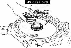
| 2. Place the rotor on the support so that
the internal gear is facing downward. Using puller tool 49-0813-240
(or equivalent) without its adaptor ring, press the bearing out of the
rotor. Being careful not to damage the internal gear. |
| 3. Place the rotor on the support with
the internal gear facing upward. Place the new rotor bearing on the
rotor so that the bearing lug is in line with the slot of the rotor
bore. |
| 4. Remove the screws which attach the
adaptor ring to the special tool. Using the special tool and adaptor
ring, press fit the new bearing until
the bearing is flush with the rotor boss. | |
|
|
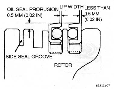
Oil Seal Inspection
|
|
See Figures 358 and
359
|
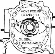
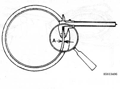
| 1. Examine the oil seal while it is mounted
in the rotor. |
| 2. If the width of the oil seal lip is
greater than 0.020 in. (0.5mm), replace the oil seal. , |
| 3. If the protrusion of the oil seal is
greater than 0.020 in. (0.5mm), replace the seal. |
|
| Oil Seal Replacement |
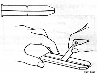
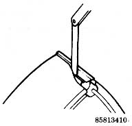
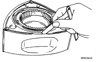
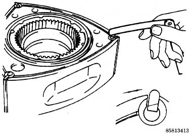
| 1. Pry the seal out by inserting a small
prybar into the slots on the rotor. Be careful not to deform the lip
of the oil seal if it is to be reinstalled. |
| 2. Fit both the oil seal springs into
their respective grooves, so that their ends are facing upward and their
gaps are opposite each other on the rotor. |
| 3. Insert a new 0-ring into each of the
oil seals. Before installing the 0-rings into the oil seals, fit each
of the seals into its proper groove on the rotor. Check to see that
all of the j seals move smoothly and freely. |
| 4. Coat the oil seal groove and the oil
seal with clean engine oil. |
| 5. Gently press the oil seal into the
groove with your fingers. Be careful not to distort the seal. Be sure
that the white mark is on the bottom side of each seal when it is installed. |
| 6. Repeat the installation procedure for
the oil seals on both sides of each rotor. |